
Facilitating Sensor Communication Through AD2 Using an Expansion Board
A senior design project that students worked on for this past year involved equipping extra features onto an Analog Devices 2, tailored to its typical Senior Design lab applications.
May 23, 2023 ![]() Kyli Dokes
Kyli Dokes
Student learn best by doing, so ECE has adopted the Analog Discovery 2 (AD2) unit throughout our curricula, aiming to accelerate and deepen learning, and have more fun. The AD2 is a portable and full-featured toolbox that can measure, visualize, generate, record, and control both analog and digital signals. It packs enough punch that it can be used to study and design the vast majority of circuits and signals in our ECE program, augmenting hands-on experiences with traditional desktop workstations.
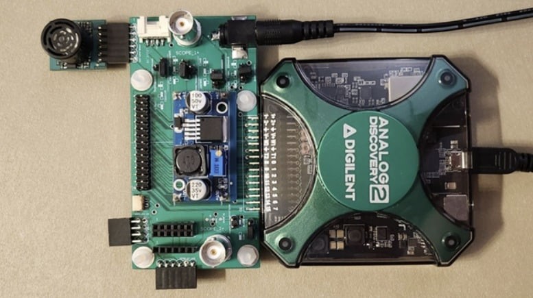
Because of the ever-increasing popularity of the bring-your-own-device (BYOD) trend, students tend to bring their own laptops and AD2s to the lab. Thus, the goal of this project was to create an add-on module that allows the students to equip their personally-owned devices with the features of lab-owned equipment, allowing them to set up a test bench environment capable of expediting the prototyping process from the comfort of their own devices. The add-on board would allow students to skip the low-level development surrounding a sensor’s implementation and instead evaluate its function straight away to see if it fits their needs, potentially cutting out weeks of R&D. Once a sensor is chosen, the students can focus on their own product, knowing that they have chosen a device that delivers useful data.
To deliver the best possible product, a survey was sent out to students and faculty of the ECE department at NC State. It allowed them to report features they felt were missing from a standalone AD2, among which the top responses were collected and formed into the basis for this project. The key features are: increasing available power, monitoring current, adding 8 additional analog inputs, providing common connectors, and making available a library of WaveForms scripts for common sensors. Additionally, the board was designed physically to be small enough to remain attached to the AD2 within its original case.
Available Power Increase
The AD2 sources its power from either the USB port it uses to communicate to a host computer, for a total of 0.5 W per channel, or a wall adapter connected via barrel jack, for a total of 2.1 W per channel. The total current output is 700 mA either way and is backed up by overcurrent and overvoltage protection circuitry to prevent damage to the internals of the AD2.
Any higher level of power must be sourced externally, so the expansion board includes an LM2569 buck converter. Its input range is 3 V to 40 V, with an adjustable output between 1.5 V and 1.5 V less than the input. It is rated for a maximum current of 3 A. With it, higher-power devices such as servos, LED strips, or displays can be tested through the WaveForms software.
Current Monitoring
The AD2 can only measure voltages of ±50 V via its two scope channels. In order to support current and power monitoring, a shunt resistor/current sense amplifier (INA190A1IDCKR) and a hall effect sensor (TMCS1108A4UQDR) are included in the expansion board. The shunt resistor/current sense amplifier is intended to measure currents up to 1.32 mA with a sensitivity of 128 nA while the hall effect measures up to 10.75 A with a sensitivity of 0.8 mA.
Additional Analog Inputs
The AD2’s scope has two differential probe channels operating at up to 100 MS/s with a 14-bit range. To increase the number of analog inputs, the expansion board contains two 12-bit ADCs (ADS1015IRUGR), usable as four differential probe channels or eight single-ended probe channels. The chips communicate via I²C and operate between 128 S/s and 3.3 kS/s.
Common Connectors
The AD2 uses a 30 pin standard header to provide access to its power, analog, and digital features. To expand upon this 30-pin connection and to increase the ease of communication between common sensors and the AD2, various connectors are placed around the expansion board. These are two BNCs, one Grove connector, one Qwiic connector, and 5 Pmod headers, shown in the expansion board’s function diagram below.
Waveforms Scripting Libraries
Using WaveForms workspaces, “presets” for various sensors, mainly Pmods, were created and made available to the user. A global readme provides instructions on downloading and setting up a workspace, with sensor-specific details explained within the workspace. In this way, a student can set up and use a sensor with ease, allowing the student to focus on the sensor’s data output and evaluate its usefulness.
Original article from Digilent